1. Assess the object:
The compressor had a number of loose cables which were restricting access and entangling during maintenance and repair operations.
We wanted to scan the internal dimensions of the compressor to understand what spacing and voids we had to design into for the bespoke bracketry.
Black metal parts of the compressor were more difficult to scan (dark and shiny!). To counter this we used dry shampoo to coat the areas to create a scannable matte finish.
2. Apply scan target markers:
Applied target markers on the inside of the compressor to help the scanner align and merge multiple scan angles accurately. Due to the size and colour of the compressor’s components, markers were placed in clusters.
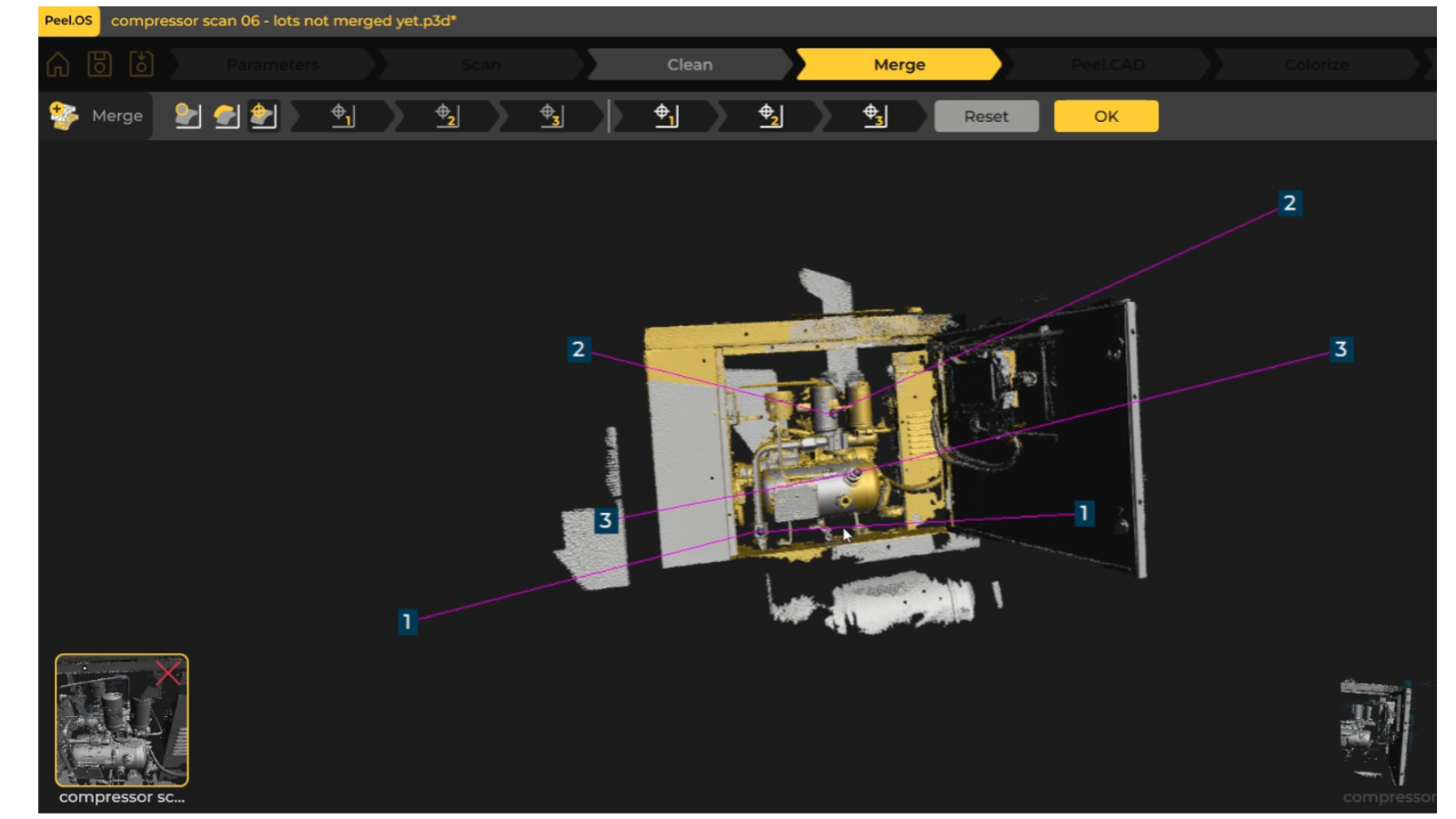
3. Scanning the complete section & merging scans:
Captured multiple scans from different angles to gain maximum scan data. Once completed, the scans were merged into a single, complete scan. As we worked on only specific areas of the compressor, we only scanned those appropriate to the design brief, to reduce data overload.
4. Generating a digital model of the compressor:
Using Peel.Cad software, used key points of the scan as a reference for building a simplified digital version of our compressor, showing key data points. This was exported into our CAD software from which the brackets could be designed using exact measurements.
5. CAD bracketry designs:
Designed 6 bespoke brackets using the data from the digital compressor model. Design iteration of each bracket was faster because measurements were readily accessible and could be cross-referenced easily in CAD from the digital model.
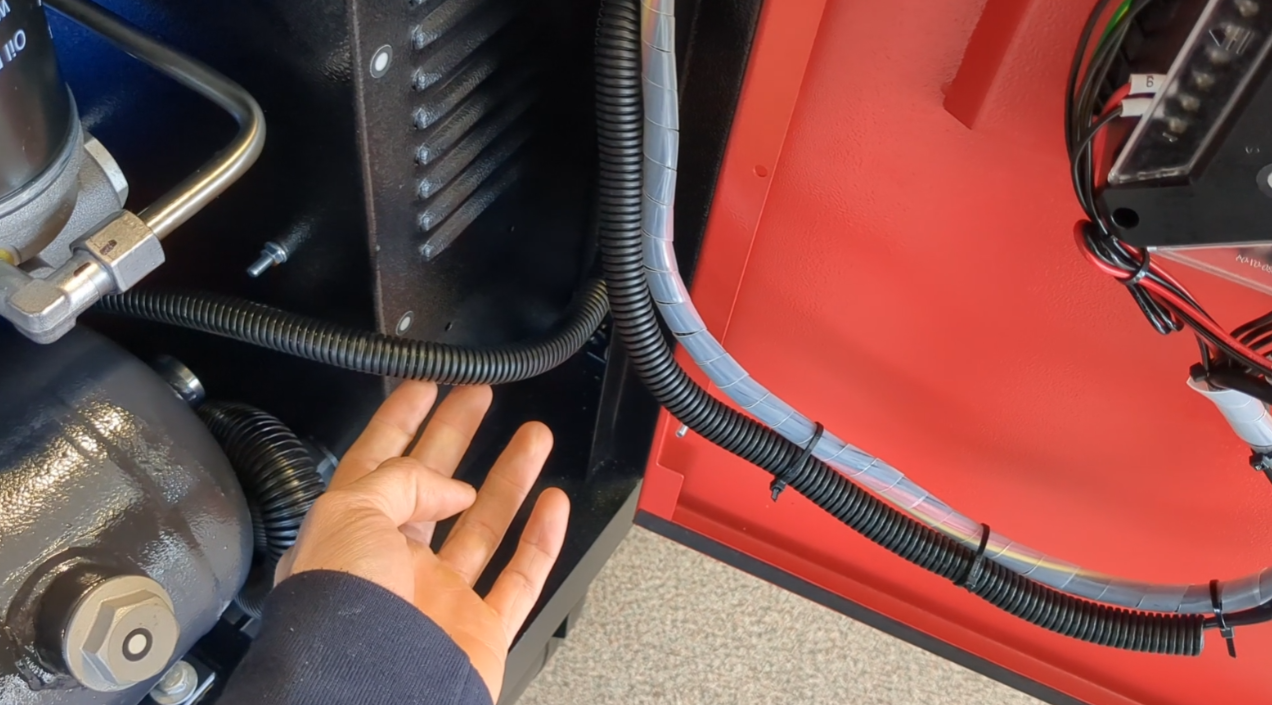
Original cables hanging loose, restricting access and entangling during maintenance and repair procedures
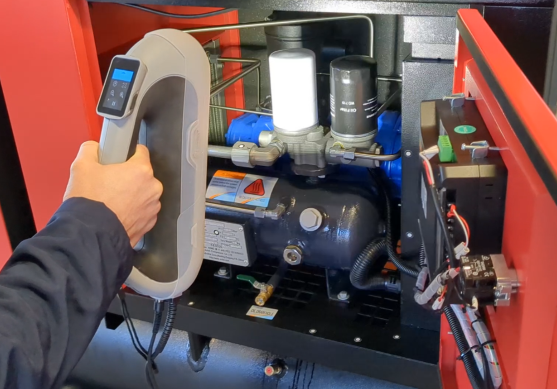
3D scanning the compressor internals using Peel 3 scanner. Target markers help scanner to align