Redesigning a Press Tool for 3D Printing
A Practical Example of DfAM in Action
Wednesday 9th July 2025
Additive Manufacturing (AM) isn't just about printing parts, it's about rethinking how those parts are designed and manufactured. As in all forms of manufacturing, the appropriate design of a part for that particular manufacturing method is essential. Take for example injection moulding, you design in draft angles and considerations for part release from the mould. When 3D printing, the consideration of the design for additive manufacture is no less important.
In this project, we set out to re-engineer a press tool using AM principles. We want to demonstrate how redesigning for 3D printing (DfAM) can reduce costs, shorten lead times, and improve tool performance, all while maintaining the functional integrity required in industrial settings.
Why 3D print a press tool? Press tools are typically CNC machined. This process can be very costly (typically £000s per tool) and is often cost prohibitive for complex or low-volume tooling. What’s more, often parts are not adapted or improved (i.e. stick with “making-do”) because to produce a new press tool is too expensive for each design change or new feature.
By 3D printing the tool, we dramatically lower the cost and reduce the lead time for production.
3D printed tool:
- 4-6 hours design time
- 20 hours print time
- Total cost of just £100
Why 3D Print a Press Tool?
A press tool is used to shape sheet metal through mechanical deformation, commonly seen in automotive, aerospace, and industrial applications. These tools are typically machined from metal using CNC processes for strength and precision. But with that precision comes a hefty price tag, especially for complex designs or low-volume production.
That’s where Additive Manufacturing, and more specifically, Design for Additive Manufacturing (DfAM) comes into play.
Why Redesign Instead of Just Print?
Simply printing the original tool design using AM technologies wouldn’t cut it. Without adaptation, the printed tool would fail after a single iteration due to insufficient strength. The goal was to make the part functional and durable. So instead of trying to replicate the traditional part, we adapted the design to be 3D printed.
Key Design Changes and Strategies
Before adjusting the design, we selected our printing method and material. For this application we used Markforged Onyx (PA66 blend) – a Nylon material with micro-carbon fibres with Continuous Carbon Fibre for reinforcement. Our printer of choice was the Markforged FX10. We also used off-the-shelf components – a standard aluminium block.
Our redesign focused on internal reinforcement, not external geometry changes. Without reinforcement, the tool would not survive a single cycle.
The part was strengthened using continuous Carbon Fibre reinforcement along with the integration of a machined aluminium block (off-the-shelf component), which provided additional structural support.
Given the geometry of the part, concentric fibre placement was chosen over isotropic, as it better suited the stress distribution within the design.
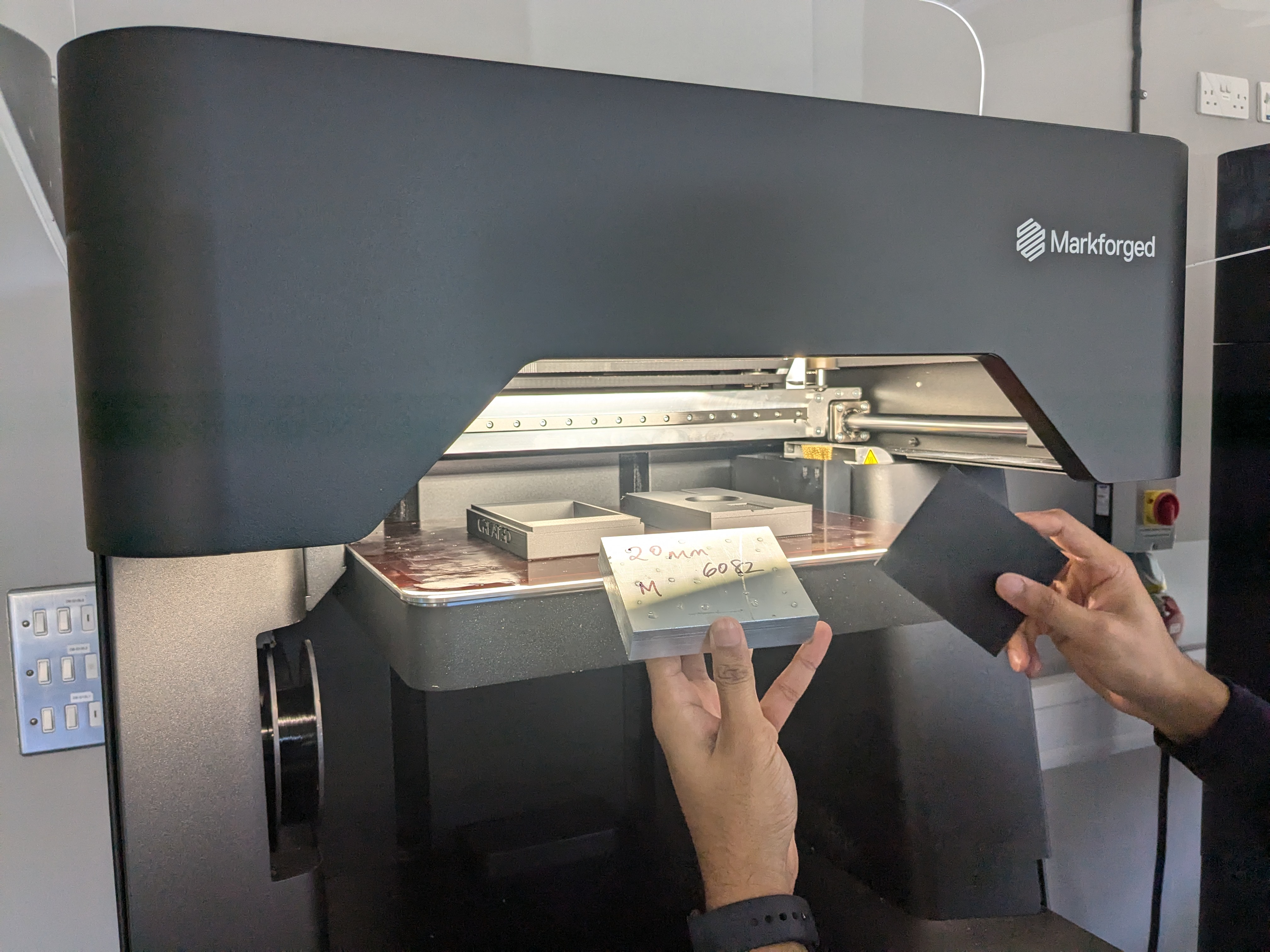
Embedding aluminium block into the tool during the printing process.
Here's what we did:
1. Continuous Carbon Fibre Reinforcement: Used to strengthen critical load paths inside the part. We selected concentric fibre placement over isotropic due to how the stresses travelled through the geometry
2. Machined Aluminium Insert: An off-the-shelf aluminium block was integrated into the design to provide rigidity and withstand compression forces
3. Wall and Fibre Strategy: Considerable attention was paid to filament flow, fibre layout, and wall structure. This ensured the tool could reliably withstand compressive forces during forming
Our reinforced version has already completed 5 successful forming operations with no visible wear or damage.
The Results: Durable, Cost-Effective, and Fast
The 3D printed press tool is now engineered for durability and function and it was produced in only 24 hours.
- Stronger and better equipped to withstand stress and compression
- More economical to produce compared to CNC machining, especially for low-volume applications
- Faster to iterate and modify, thanks to shorter print times and accessible material strategies
It’s not just about making the tool cheaper, it’s about making it better, smarter, and more fit for purpose using additive technology.
Tips for Designing Tools with AM in Mind
If you’re thinking about using AM for jigs, fixtures, or low-volume tooling, here are some practical DfAM considerations:
- Plan your pauses: When printing parts that require embedded components, minimise the time between pause and resume. Delays can leave a visible seam or compromise layer adhesion.
- Design around the actual off-the-shelf parts: Components like aluminium inserts may vary slightly in size. Design some tolerance or adjustability into your model to avoid misalignment or rework.
- Fibre placement strategy matters: Use concentric fibre reinforcement for parts with directional stress paths; isotropic for uniform loading. Don’t overuse Carbon Fibre, it adds cost and time without benefit unless it's strategically placed.
- Smart material usage: Flooding your part with Carbon Fibre or increasing infill of Onyx isn’t always the answer. Use the right material where it counts, in the right quantities.
Why DfAM Matters
This project shows the value of expertise in Additive design. Knowing how and where to apply reinforcement, integrate hybrid materials, and leverage DfAM principles is what makes the difference between a failed print and a production-ready tool.
If you’re exploring AM for tooling or production parts, our team can help you get the most from the technology, whether that’s through part re-design, AM consultation or in-house printing support.